Tuesday, December 31, 2019

#Wired Gesture controlled robot

Gyroscope Controlled Robot (Wired)


Gyroscopes are used in mostly all devices. The most common example is the smartphones. The Gyro sensors are used to sense the angular velocity and using that data we can control the movement of the robot. Unlike accelerometers which measure linear acceleration, the Gyroscope sensors adds an additional dimension to the accelerometer thus allowing us to measure the angular velocity.
Today we will learn to make a Gyroscope controlled robot using Arduino and GY521 Gyroscope sensor.

Working :

The gyroscope sensor is also known as the tilt sensor. It senses its movements and provides the values to the arduino. The gyroscope module works in all the three axis namely the x,y and z. When the arduino receives these values it uses them with the if else statements to drive the motors accordingly. 
This project is a wired project. i.e. The Arduino and Gyro sensor is connected to each other using wires. This project can be used for surveillance and the only disadvantage with this project is its wired connections.

Components used in this project :


1. Arduino Uno.

2. GY-521 MPU-6050 Gyroscope sensor.

3. Motor Driver Module.

4. Metal chassis and wheels.

5. Connecting wires.

6. Double sided tape.

7. Batteries or adapter to power the board.

Circuit Diagram :

The circuit diagram for this project is shown below. Do all the connections accordingly.


You can also download the circuit diagram by clicking HERE .

Place all the components on metal chassis and fix them with the help of some double sided tape.

Here are some screen shots of the project.


Now connect the Arduino to your PC and upload the code.

CODE :

#include<Wire.h>
const int MPU_addr=0x68;  // I2C address of the MPU-6050
int16_t AcX,AcY,AcZ,Tmp,GyX,GyY,GyZ;
 const int trigPin=13;
 //Motor A
const int motorPin1  = 5;
const int motorPin2  = 6;
//Motor B
const int motorPin3  = 10;
const int motorPin4  = 9;
void setup()
{
  pinMode(trigPin,OUTPUT);
  pinMode(motorPin1, OUTPUT);
pinMode(motorPin2, OUTPUT);
pinMode(motorPin3, OUTPUT);
pinMode(motorPin4, OUTPUT);
  Wire.begin();
  Wire.beginTransmission(MPU_addr);
  Wire.write(0x6B);
  Wire.write(0); 
  Wire.endTransmission(true);
  Serial.begin(9600);
}
void loop(){
  Wire.beginTransmission(MPU_addr);
  Wire.write(0x3B);
  Wire.endTransmission(false);
  Wire.requestFrom(MPU_addr,14,true);
  AcX=Wire.read()<<8|Wire.read(); 
  AcY=Wire.read()<<8|Wire.read();
  AcZ=Wire.read()<<8|Wire.read();
  Tmp=Wire.read()<<8|Wire.read();
  GyX=Wire.read()<<8|Wire.read();
  GyY=Wire.read()<<8|Wire.read();
  GyZ=Wire.read()<<8|Wire.read();
  Serial.print("AcX = "); Serial.print(AcX);
  Serial.print(" | AcY = "); Serial.print(AcY);
  Serial.print(" | AcZ = "); Serial.print(AcZ);
  Serial.print(" | Tmp = "); Serial.print(Tmp/340.00+36.53);
  Serial.print(" | GyX = "); Serial.print(GyX);
  Serial.print(" | GyY = "); Serial.print(GyY);
  Serial.print(" | GyZ = "); Serial.println(GyZ);
  if(AcX<-6000&&-11000)
  {
    digitalWrite(trigPin,HIGH);
    digitalWrite(motorPin1, LOW);
    digitalWrite(motorPin2, HIGH);//FORWARD
    digitalWrite(motorPin3, HIGH);
    digitalWrite(motorPin4, LOW);
  }
  else if(AcX>4000&&6000)
  {
   digitalWrite(motorPin1, HIGH);
    digitalWrite(motorPin2, LOW);//REVERSE
    digitalWrite(motorPin3, LOW);
    digitalWrite(motorPin4, HIGH);
  }
   else if(AcY<-7000&&-5000)
  {
   digitalWrite(motorPin1, HIGH);
    digitalWrite(motorPin2, LOW);//LEFT
    digitalWrite(motorPin3, HIGH);
    digitalWrite(motorPin4, LOW);
  }
  else if(AcY>5000&&12000)
{
    digitalWrite(motorPin1, LOW);
    digitalWrite(motorPin2, HIGH);//RIGHT
    digitalWrite(motorPin3, LOW);
    digitalWrite(motorPin4, HIGH);
}
  else
  {
    digitalWrite(trigPin,LOW);
    digitalWrite(motorPin1, LOW);
    digitalWrite(motorPin2, LOW);//STOP
    digitalWrite(motorPin3, LOW);
    digitalWrite(motorPin4, LOW);
  }
  delay(333);
}

You can also download the code from HERE .

After this power the Arduino and Motor driver and that's it. Your project is ready to be tested.

Wednesday, December 18, 2019

#Wirelss gesture controlled robot

Hand Gesture Controlled Robot using Arduino

In this project, we have designed a simple Hand Gesture Controlled Robot using Arduino. This Hand Gesture Controlled Robot is based on Arduino Nano, MPU6050, RF Transmitter-Receiver Pair and L293D Motor Driver.
Even though the title says it as a Hand Gestured Controlled Robot, technically this robot is controlled by the tilt of the hand. 

Table of Contents

Saturday, December 14, 2019

#line follower robot

How to make line follower robot- using Arduino ??

Line follower Robot is a machine which follows a line, either a black line or white line. Basically there are two types of line follower robots: one is black line follower which follows black line and second is white line follower which follows white line. Line follower actually senses the line and run over it.

Concepts of Line Follower

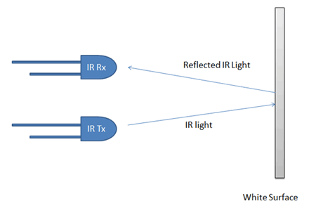
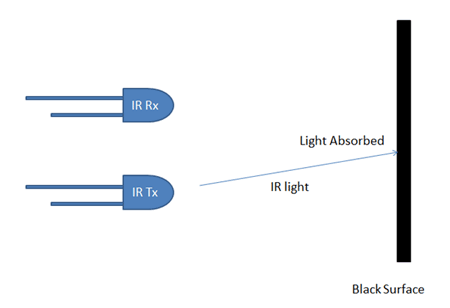
Concept of working of line follower is related to light. We use here the behavior of light at black and white surface. When light fall on a white surface it is almost full reflected and in case of black surface light is completely absorbed. This behavior of light is used in building a line follower robot.
Concept of White Line Follower Robot
Concept of Black Line Follower Robot
In this arduino based line follower robot we have used IR Transmitters and IR receivers also called photo diodes. They are used for sending and receiving light. IR transmits infrared lights. When infrared rays falls on white surface, it’s reflected back and catched by photodiodes which generates some voltage changes. When IR light falls on a black surface, light is absorb by the black surface and no rays are reflected back, thus photo diode does not receive any light or rays.
Here in this arduino line follower robot when sensor senses white surface then arduino gets 1 as input and when senses black line arduino gets 0 as input.

Circuit Explanation

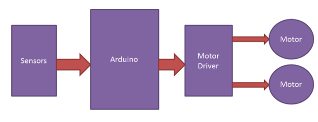
The whole arduino line follower robot can be divided into 3 sections: sensor section, control section and driver section.

Sensor section:
This section contains IR diodes, potentiometer, Comparator (Op-Amp) and LED’s. Potentiometer is used for setting reference voltage at comparator’s one terminal and IR sensors are used to sense the line and provide a change in voltage at comparator’s second terminal. Then comparator compares both voltages and generates a digital signal at output. Here in this line follower circuit we have used two comparator for two sensors. LM 358 is used as comparator. LM358 has inbuilt two low noise Op-amps.

Control Section:
Arduino Pro Mini is used for controlling whole the process of line follower robot. The outputs of comparators are connected to digital pin number 2 and 3 of arduino. Arduino read these signals and send commands to driver circuit to drive line follower. 

Driver section:
Driver section consists motor driver and two DC motors. Motor driver is used for driving motors because arduino does not supply enough voltage and current to motor. So we add a motor driver circuit to get enough voltage and current for motor. Arduino sends commands to this motor driver and then it drive motors.

Working of Line Follower Robot using Arduino

Working of line follower is very interesting. Line follower robot senses black line by using sensor and then sends the signal to arduino. Then arduino drives the motor according to sensors' output.
Working of Line Follower Robot using Arduino
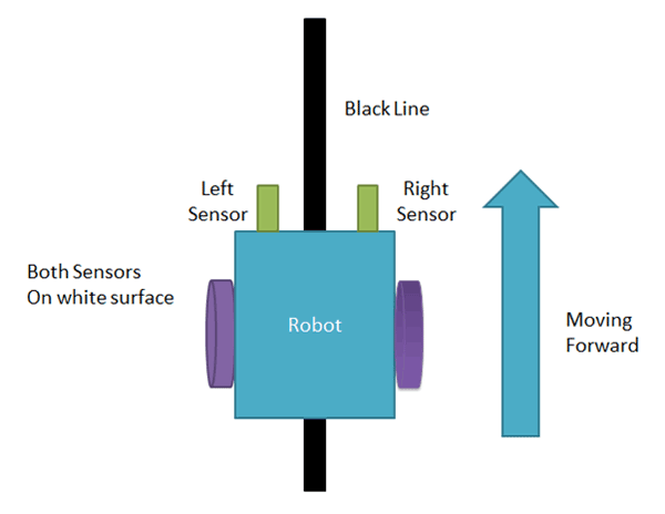
Here in this project we are using two IR sensor modules namely left sensor and right sensor. When both left and right sensor senses white then robot move forward.
Working of Arduino Line Follower Robot
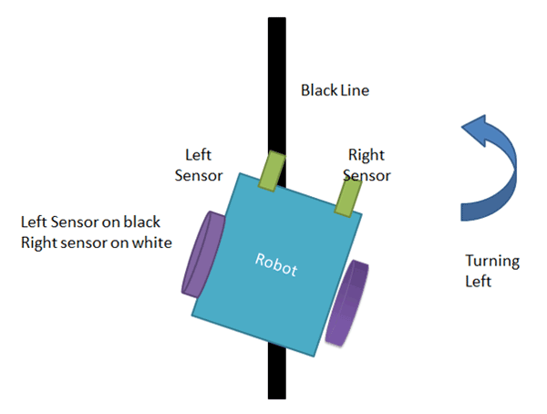
If left sensor comes on black line then robot turn left side.
Turning left to line follower robot using arduino
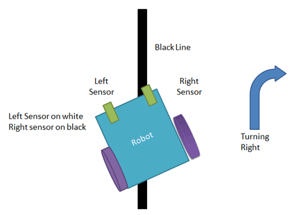
If right sensor sense black line then robot turn right side until both sensor comes at white surface. When white surface comes robot starts moving on forward again.
Turning right to line follower robot
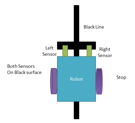
If both sensors comes on black line, robot stops.
Stopping Arduino Line Following Robot

Code-

int s1= A2;
int s2= A4;
int R1=7;
int R2=8;
int L1=10;
int L2= 11
void setup(){
    Serial.begin(115200);
    pinMode(s1,INPUT);
    pinMode(s2,INPUT);
    pinMode(L1,OUTPUT);
    pinMode(L2,OUTPUT);
    pinMode(R1,OUTPUT);
    pinMode(R2,OUTPUT);
}

void loop(){
    int s1 = digitalRead(A1);
    int s2 = digitalRead(A4);
    Serial.print(s1);
    Serial.print("\t");
    Serial.print(s2);
    Serial.print("\t");
  
    
//FORWARD
   
 if(s1==1 && s2 == 1){
       digitalWrite(R1,HIGH);
       digitalWrite(R2,LOW);
       digitalWrite(L1,HIGH);
       digitalWrite(L2,LOW);
        
    }
       
    }
    //TURN LEFT
  if(s1 == 0 && s2 == 1){
       digitalWrite(R2,LOW);
       digitalWrite(R1,LOW);
       digitalWrite(L2,HIGH);
       digitalWrite(L1,HIGH);
      
    }
    //TURN RIGHT 
   if(s1 == 1 &&  s2 == 0){
        digitalWrite(R2,HIGH);
        digitalWrite(R1,HIGH);
        digitalWrite(L2,LOW);
        digitalWrite(L1,LOW);
    }
    
}

Friday, November 29, 2019

How to make obstacle Avoiding robot using Arduino ??


Obstacle Avoiding Robot using Arduino

A simple project on Obstacle Avoiding Robot is designed here. Robotics is an interesting and fast growing field. Being a branch of engineering, the applications of robotics are increasing with the advancement of technology.

Obstacle Avoiding Robot using Arduino Image 2

The concept of Mobile Robot is fast evolving and the number of mobile robots and their complexities are increasing with different applications.
There are many types of mobile robot navigation techniques like path planning, self – localization and map interpreting. An Obstacle Avoiding Robot is a type of autonomous mobile robot that avoids collision with unexpected obstacles.
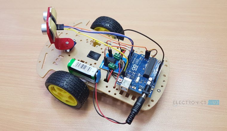
In this project, an Obstacle Avoiding Robot is designed. It is an Arduino based robot that uses Ultrasonic range finder sensors to avoid collisions. 

Hardware Required

  • Arduino Uno 
  • Ultrasonic Range Finder Sensor – HC – SR04  
  • Motor Driver IC – L293D 
  • Servo Motor (Tower Pro SG90)  
  • Geared Motors x 2 
  • Robot Chassis  
  • Power Supply 
  • Battery Connector
  • Battery Holder

Component Description

Arduino Uno

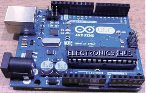
Arduino Uno is an ATmega 328p Microcontroller based prototyping board. It is an open source electronic prototyping platform that can be used with various sensors and actuators.
Arduino Uno has 14 digital I/O pins out of which 6 pins are used in this project.

Arduino Uno Board
HC – SR04

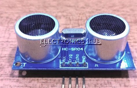
It is an Ultrasonic Range Finder Sensor. It is a non-contact based distance measurement system and can measure distance of 2cm to 4m.
Ultrasonic Sensor

L293D

It is a motor driver which can provide bi-directional drive current for two motors. 

Servo Motor 

The Tower Pro SG90 is a simple Servo Motor which can rotate 90 degrees in each direction (approximately 180 degrees in total).  

Design of Obstacle Avoiding Robot using Arduino

Arduino is the main processing unit of the robot. Out of the 14 available digital I/O pins, 7 pins are used in this project design.
The ultrasonic sensor has 4 pins: Vcc, Trig, Echo and Gnd. Vcc and Gnd are connected to the +5v and GND pins of the Arduino. Trig (Trigger) is connected to the 9th pin and Echo is connected to 8th pin of the Arduino UNO respectively. 
A Servo Motor is used to rotate the Ultrasonic Sensor to scan for obstacles. It has three pins namely Control, VCC and GND. The Servo Control Pin is connected to pin 11 of Arduino while the VCC and GND are connected to +5V and GND.  
L293D is a 16 pin IC. Pins 1 and 9 are the enable pins. These pins are connected to +5V.  Pins 2 and 7 are control inputs from microcontroller for first motor. They are connected to pins 6 and 7 of Arduino respectively.
Similarly, pins 10 and 15 are control inputs from microcontroller for second motor. They are connected to pins 5 and 4 of Arduino. Pins 4, 5, 12 and 13 of L293D are ground pins and are connected to Gnd.
First motor (consider this as the motor for left wheel) is connected across the pins 3 and 6 of L293D. The second motor, which acts as the right wheel motor, is connected to 11 and 14 pins of L293D.
The 16th pin of L293D is Vcc1. This is connected to +5V. The 8th pins is Vcc2. This is the motor supply voltage. This can be connected anywhere between 4.7V and 36V. In this project, pin 8 if L293D is connected to +5V supply. 
NOTE: The power supply to the Motor Driver i.e. Pins 1 (enable 1), 8 (VCC2), 9 (enable 2) and 16 (VCC1) should be given a seperate power supply.
Motor Driver boards are available with on – board 5V voltage regulator. A similar one is used in the project. 
If the above Circuit Diagram of the Obstacle Avoiding Robot is unclear, the following image might be helpful. 

Working

Before going to working of the project, it is important to understand how the ultrasonic sensor works. The basic principle behind the working of ultrasonic sensor is as follows:
Using an external trigger signal, the Trig pin on ultrasonic sensor is made logic high for at least 10µs. A sonic burst from the transmitter module is sent. This consists of 8 pulses of 40KHz.
The signals return back after hitting a surface and the receiver detects this signal. The Echo pin is high from the time of sending the signal and receiving it. This time can be converted to distance using appropriate calculations.
The aim of this project is to implement an obstacle avoiding robot using ultrasonic sensor and Arduino. All the connections are made as per the circuit diagram. The working of the project is explained below.
When the robot is powered on, both the motors of the robot will run normally and the robot moves forward. During this time, the ultrasonic sensor continuously calculate the distance between the robot and the reflective surface.
This information is processed by the Arduino. If the distance between the robot and the obstacle is less than 15cm, the Robot stops and scans in left and right directions for new distance using Servo Motor and Ultrasonic Sensor. If the distance towards the left side is more than that of the right side, the robot will prepare for a left turn. But first, it backs up a little bit and then activates the Left Wheel Motor in reversed in direction. 
Similarly, if the right distance is more than that of the left distance, the Robot prepares right rotation.  This process continues forever and the robot keeps on moving without hitting any obstacle.
NOTE
  • As the project is based on Arduino, the programming is very easy and can be easily modified.
  • Doesn’t require the Arduino Motor Shield.
  • When using a 9V battery, at least 2 such batteries are needed to power the robot. It is better to use 2 9V batteries (one for Arduino, Ultrasonic sensor, Servo Motor and the other one for L293D and motors).
  • The Ultrasonic sensor should not be connected directly to power supply as it might affect the normal performance.
  • Instead of ultrasonic sensor, an IR transmitter – receiver pair can also be used.

Applications

  • Obstacle avoiding robots can be used in almost all mobile robot navigation systems.
  • They can be used for household work like automatic vacuum cleaning.
  • They can also be used in dangerous environments, where human penetration could be fatal.

CODE-

#include<Servo.h>
Servo SM;

#define LA 7
#define LB 8
#define RA 10
#define RB 11


const int pingPin = A5;

void setup() {
  pinMode(LA, OUTPUT);
  pinMode(LB, OUTPUT);
  pinMode(RA, OUTPUT);
  pinMode(RB, OUTPUT);

  SM.attach(A3);
  SM.write(90);
  delay(3000);


}
int distance;
void loop() {
  findDistance() ;

  if (distance > 35) {
    forward();
  }
  else {
    delay(60);
    findDistance();
    if (distance > 35) {
      forward();
    } else {
      Stop();
      SM.write(40);
      delay(500);
      findDistance();
      if (distance>35){
        SM.write(90);
        delay(1000);
        rightward();
        delay(500);
        Stop();
      }else{
        SM.write(130);
        delay(1000);
        findDistance();
        if (distance>35){
          SM.write(90);
          delay(1000);
          leftward();
          delay(500);
          Stop();
        }else{
          SM.write(90);
          delay(1000);
          rightward();
          delay(1500);
          Stop();
          
        }
      }
    }
  }
}
void forward() {
  digitalWrite(LA, HIGH);
  digitalWrite(LB, LOW);
  digitalWrite(RA, HIGH);
  digitalWrite(RB, LOW);
}
void backward() {
  digitalWrite(LA, LOW);
  digitalWrite(LB, HIGH);
  digitalWrite(RA, LOW);
  digitalWrite(RB, HIGH);
}
void leftward() {
  digitalWrite(LA, HIGH);
  digitalWrite(LB, LOW);
  digitalWrite(RA, LOW);
  digitalWrite(RB, HIGH);
}
void rightward() {
  digitalWrite(LA, LOW);
  digitalWrite(LB, HIGH);
  digitalWrite(RA, HIGH);
  digitalWrite(RB, LOW);
}
void Stop() {
  digitalWrite(LA, LOW);
  digitalWrite(LB, LOW);
  digitalWrite(RA, LOW);
  digitalWrite(RB, LOW);
}

void findDistance() {
  long duration;

  pinMode(pingPin, OUTPUT);
  digitalWrite(pingPin, LOW);
  delayMicroseconds(2);
  digitalWrite(pingPin, HIGH);
  delayMicroseconds(5);
  digitalWrite(pingPin, LOW);

  
  pinMode(pingPin, INPUT);
  duration = pulseIn(pingPin, HIGH);

  distance = microsecondsToCentimeters(duration);

  
  Serial.print(distance);
  Serial.print("distance");
  Serial.println();

  delay(100);
}

long microsecondsToCentimeters(long microseconds) {
  // The speed of sound is 340 m/s or 29 microseconds per centimeter.
  // The ping travels out and back, so to find the distance of the object we
  // take half of the distance travelled.
  return microseconds / 29 / 2;
}